Editable Two-Dimensional Paths
Export paths as standard R12 ASCII DXF polylines. The output contains coordinates and connected vertices rather than a screenshot placed inside a drawing.

Export PDF drawing paths as 2D DXF polylines for CAD inspection.
Drop files here or use the button below.
Up to 100 MB total · Files stay on your device
Preview the document here. For added content, this is a placement guide; check the saved output.
Extract supported vector drawing paths from a PDF into ASCII DXF. Each selected page becomes its own drawing. Straight segments remain linework, and curves are approximated by connected segments that a CAD application can inspect or edit.
The result is DXF, not DWG. It does not recover the source drawing's dimensions, constraints, text objects or layers. Text and raster images are excluded, and overlapping objects remain separate. Scans and text-only pages cannot supply CAD linework through this tool.
Export paths as standard R12 ASCII DXF polylines. The output contains coordinates and connected vertices rather than a screenshot placed inside a drawing.
Select the sheet pages you need. A single page downloads as DXF; multiple selected pages download in a ZIP containing separate DXF files.
Set how many DXF coordinate units correspond to one PDF point. This gives an explicit starting scale, which you should verify against a known dimension after import.
Approximate curves with a 0.1 PDF-point flatness tolerance. Page and rectangular form boundaries limit exported segments; unsupported clipping and transparency cause a refusal.
Select a PDF containing drawing paths.
Select the screenshot to enlarge it.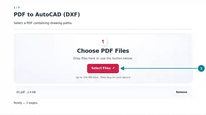
Choose pages, set coordinate scale and acknowledge the export limits.
Select the screenshot to enlarge it.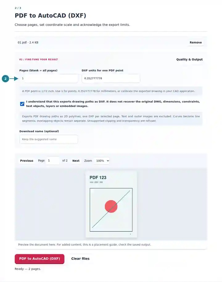
Save the drawing and verify it in a CAD application.
Select the screenshot to enlarge it.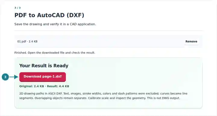
Screenshots show this toolkit using harmless sample files. Your file name, page count and settings may differ.
Path extraction can provide a starting reference when you have a vector PDF but no editable drawing. It saves tracing supported outlines by hand, while leaving the interpretation of that linework to you. A printed dimension label is excluded as text and does not establish the drawing's scale. Stroke widths, colors and dash patterns are also omitted, so rebuild those properties where they matter.
Inspect existing vector outlines before rebuilding a documented drawing with appropriate layers and dimensions.
Compare PDF paths with CAD entities and understand which original design relationships are absent.
Evaluate simple outlines as a starting reference, then check scale and geometry before any production workflow.
| Setting | What to Expect |
|---|---|
| Input | One unencrypted PDF up to 100 MiB and 500 source pages. |
| Selection and complexity | Up to 20 selected pages and 200,000 generated vertices per job. |
| Scale | A positive number up to 1,000 DXF units per PDF point. One PDF point is 1/72 inch; 0.352777778 provides an approximate millimeter conversion. |
| Output | R12 ASCII DXF polylines, one file per selected page. Curves use a 0.1 PDF-point flatness tolerance. |
| Excluded content | Text, raster images, dimensions, constraints, original layers, colors, stroke widths and dash patterns. No DWG encoder or scan tracing. |
Export one page containing a rectangular outline and set the scale to 1. Measure that rectangle in the CAD application and compare it with an independently known source dimension. Apply the required scale factor before extending the drawing. A PDF might already have been printed at a reduced size, so converting points to millimeters alone does not restore the original engineering scale.
| Situation | What to Check |
|---|---|
| No drawing paths are found | The page may be a scan or contain only text. This tool does not trace bitmap edges or turn OCR text into CAD geometry. |
| A clipping or transparency warning appears | The page uses drawing effects outside the supported exporter. Request a simpler vector PDF or the original CAD file. |
| The drawing opens at an unexpected size | Check the coordinate scale and measure a known distance. A previous print or export step may have changed the source scale. |
No. The converter writes R12 ASCII DXF, which can be opened in a compatible CAD application. Saving a verified drawing as DWG is a separate action in that application.
No. PDF paths do not preserve the source CAD relationships in a form this exporter reconstructs. Add meaningful layers, constraints and dimensions after checking the geometry.
No. Curves become polylines using a 0.1 PDF-point flatness tolerance. Inspect the resulting segment count and geometry before using them for precision work.